Multibeam Guide
Our Mission
Mapping serves as the backbone of all of our research and is one of SOI’s key focus areas for the next decade of research. As a partner of the Nippon-Foundation GEBCO Seabed 2030 Project, an international program to get a high-resolution map of the entire seafloor by 2030, we aim to contribute to the global databases of high resolution multibeam bathymetric data, as well as producing important maps for expansion of protected areas. We strive to map in remote regions, fostering a better understanding of these unknown ecosystems and how to best protect them. To achieve this, Falkor (too)’s suite of multibeam sonars was designed to cover the full range of ocean depth at high resolution: from shallow coastlines to the deepest trenches. This mapping guide is intended as an aid for future science parties you prepare for your expedition aboard Falkor (too).
Multibeam Echosounder Overview
EM124
- Specifications: Full ocean depth (11,000m) multibeam echosounder with 12kHz nominal operating frequency (FM pulses and Tx sectors typically span 10.5-13.5 kHz).
- Beamwidth 0.5° Tx with 1° Rx
- Depth Range: 20m to 11,000m
- FKt Typical Operational Range: 1000m - 6,000m
- Swath Width: up to 6 times the depth
EM712
- Specifications: High resolution mid range multibeam echosounder with an operational frequency of 40-100kHz.
- Beamwidth: 0.25° Tx with 0.5° Rx
- Depth Range: 3m - 3,600m
- FKt Typical Operational Range: 50m - 1,000m
- Swath Width: up to 5.5 times the depth
EM2040
- Specifications: High resolution and multi-frequency shallow water multibeam echosounder with an operational frequency band of 200- 700 kHz).
- Beamwidth: 0.4° Tx with 0.75° Rx
- Depth Range: <1m - 635m
- FKt Typical Operational Range: 40m- 100m
Which Multibeam Should I Use?
- In general, the best multibeam to use is dependent on depth and survey goals. An easy rule of thumb is:
- <100m : EM2040
- 100m - 1,000m : EM712
- ~1,000m : EM712 and EM124 sync’d
- >1,000m : EM124
- Each multibeam’s highest data quality will be achieved at the center of its operational range. However, while operating at the same depth, one multibeam may have a higher resolution of data while the other may have a larger swath width. We see this most often with EM712 and EM124 at 1,000m where EM712 achieves the higher resolution while EM124 achieves a larger swath. Running both multibeams simultaneously, will reduce the ping density of both echosounders, which we discuss more below.
Interference
When multiple echosounders are operating simultaneously, their pings can potentially interfere with the other echosounders that are running, making it so that neither echosounder can get clean data. Ksync, a Kongsberg product, works with the echosounder to stagger their transmission timing, allowing us to operate echosounders that would normally interfere with each other simultaneously. A word of caution: by staggering the transmissions, Ksync also increases the standby periods of each echosounder, ultimately reducing the ping density while running multiple echosounders.
Ksync
List of Syncable Echosounders
Currently, the following echosounders can be synchronized via our Ksync software:
- EM124- Deep Water Multibeam
- EM712- Medium Range Multibeam
- EM2040- Shallow Water Multibeam
- SU90- Collision Avoidance Forward Facing Sonar
- SBP29- Sub Bottom Profiler
- EK80- Mid Water Echosounder
- OS38- Deep Range ADCP
- EA640- Full Range Single Beam Echosounder
Common Combinations
Different survey goals call for different combinations of echosounders. Below are some common combinations that work well together with Ksync.
Very Shallow Water Mapping
- <100m
- EM2040 and SU90
- All other echosounders secured.
Shallow Water Mapping
- 50m - 300m
- EM2040, EM712 and SU90
- Can also sync SBP29
- All other echosounders secured.
Shallow-Mid Water Mapping
- 100m - 1,000m
- EM712 and SU90
- Can also sync SBP29
- All other echosounders secured.
Mid Water Mapping
- 800m - 1200m
- EM712 and EM124
- Can sync EM124 with SBP29 via EM Trigger
Deep Water Mapping
- 1,000m - 11,000m
- EM124, SBP29, WH300 and OS38
- Can also sync EK80
Environmental Considerations to Surveys
The design of Falkor (too) makes our echosounder data susceptible to environmental conditions, most notably from bubble sweeps during moderate- heavy weather. These bubble sweeps occur most often at high ship speeds when the ship is headed into the weather.
Survey Recommendations
The following steps can be taken to minimize the effect of weather on the echosounder data quality.
- Reduce vessel speed: normal survey speeds for FKt are ~6 knots, reducing to 4 kts can reduce the bubble sweeps down the hull, which interrupts the echosounder transmission.
- Change survey direction so the ship does not have to survey into weather: the greatest amount of bubble sweeps occur when the ship is heading into weather , which can be reduced by adjusting the survey direction so the weather is either at our beam or quarter.
- Reduce angular coverage: In heavy weather, the outside beams generally suffer the most, so bringing the beams in to reduce the overall angular coverage can improve data quality to a certain extent.
Multibeam Coverage
Multibeam coverage is dependent on the echosounder used, depth of the seabed, angular coverage and environmental conditions. Generally shallow topography= less coverage and higher resolution, deeper topography= more coverage and less resolution.
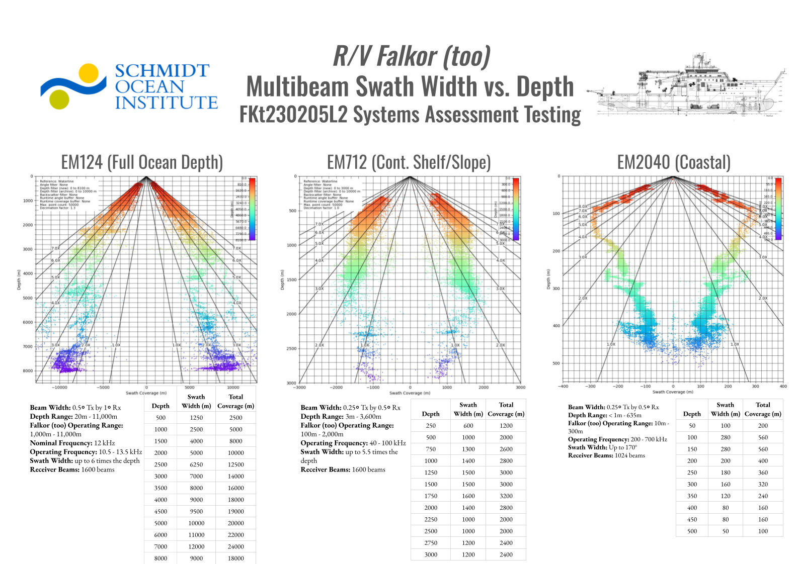
Swath Width
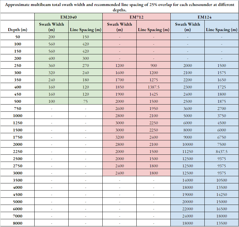
Knowing the swath width of a echosounder will help in determining line spacing and survey coverage. The table below shows the approximate swath coverage between the different echosounders within different depth ranges that you can use to guide line plans for your cruise.
Overlap Suggestions
Swath coverage constantly shifts larger and smaller during a survey as a result of rugged terrain. Occasionally, terrain at the edges of swaths can cause shadowing or holes, which can cause your observed swath distance to be smaller than expected. In addition, the edges of the swaths are generally noisy and subject to holes. Therefore, we suggest planning for 20-25% overlap between each line to achieve a good multibeam product.
Edge Mapping Surveys
The marine technicians on Falkor (too) work closely with the bridge officers to achieve the highest data quality for the survey. It is a fairly routine practice to edge-map under the deck officer and marine technicians’ direction, using the line plan as a guide. The bridge officers have a real time display of the multibeam giving them an active role to maneuver the ship with the changing terrain. This allows us to weave in and out as the topography allows, maximizing swath coverage without risking holes to achieve the highest coverage survey data.
Swath Width and Line Spacing Table
Multibeam Resolution
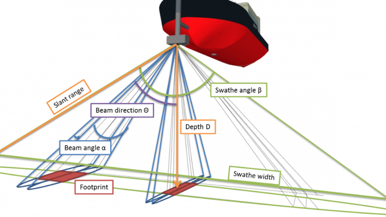
The resolution of the multibeam data can be described by the sounding density along track and across track.
Resolution is dependent on several factors:
- Water Depth
- Physical Characteristics of the Echosounder
- Angular Coverage
- Ship’s Speed
- Conditions that Affect the Echosounder’s Signal to Noise Ratio
- Ship Noise
- Environmental Conditions
- Echosounder Performance
Along Track
The distance between soundings in the direction the ship is moving. This is generally dependent specifically on depth and speed. The deeper the seafloor, the larger amount of time it takes for sound to travel to the seabed and back. The faster the ship’s speed, the more distance is covered between each ping.
Across Track
The distance between soundings across the swath and perpendicular to the vessel’s motion. This is dependent on a multitude of factors including a echosounder’s physical characteristics, the set angular coverage, and depth.
How do I increase the resolution of my survey?
- Reduce speed.
- Decrease angular coverage.
- Increase swath overlap / multiple passes over the same area
- Utilize dual swath mode (dual swath mode has been known to cause issues with bottom tracking).
Does Resolution = Object Detection?
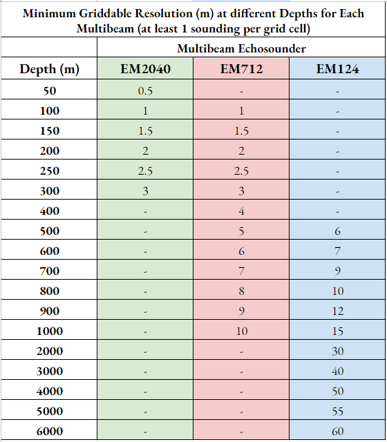
It’s important to note that resolution does not directly equate to object detection. Just because you can grid your survey to a resolution of 25 meters, does not mean you can detect a 25m object. See Object Detection section for more information.
Multibeam Resolution Table
Object Detection
Resolution Principles
Sounding density, although closely related to resolution, is a better gauge of what size object is detectable by the multibeam. To be able to detect an object, you generally need at least 3-6 soundings to hit the target.
Different Variables that affect Object Detection
The same variables that affect resolution also contribute to object detection. The higher resolution data you can achieve, the higher the likelihood of detecting objects with a multibeam echosounder.
- Depth: shallower depths, mean more concentrated beams, higher chance of detection
- Speed: slower survey speeds means more concentrated along track pings, higher chance of detection
- Angular Coverage: smaller beam angles provide more concentrated beams across track, higher chance of detection
- Beam Width: is a characteristic of the sounder. Narrower beams detect smaller targets. Higher frequencies produce narrower beams. Use the best sounder available to match your needs.
- Echosounder Settings: settings like dual swath mode can increase the quantity of beams within a given swath.
Target Detection Principles
To achieve target detection, you need to have a high enough sounding density so that a few soundings hit your target. In general, speed, angular coverage, depth, echosounder mode and target size will all affect what a multibeam can detect. However, it’s important to understand that despite a multibeam technically detecting a target, this doesn’t mean that target will be able to be distinguished from other noise/ terrain by the human eye. Some factors that can affect human detection include target shape and material, height from seabed, surrounding topography, and more- but this is out of the scope of this document and can be discussed further with the ship’s Marine Technicians. Some steps that can be taken to help recognize a target include: slowing down, reducing angular coverage, or conducting multiple passes in different directions/ place in the swath. The backscatter/seabed display is also a powerful tool to help recognize a target, as it can aid in distinguishing harder, more reflective surfaces.
AUV’s and Target Detection
Multibeams are not target detection echosounders. We often rely on luck and optimal conditions when a target is detected with a multibeam. AUV’s are the better option as they can survey at shallow heights above the seafloor with multibeams, synthetic aperture sonars (SAS) and cameras.
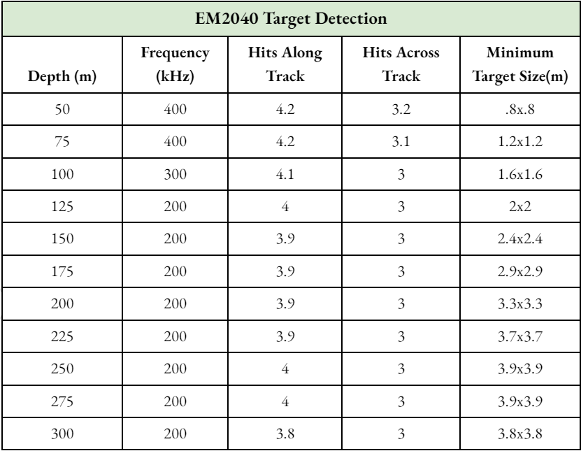
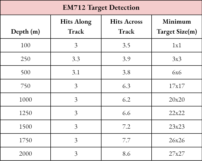
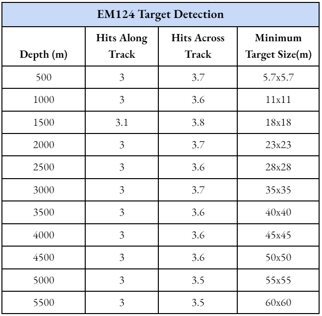
Target Detection Tables
The tables below are calculated w/ Kongsberg’s EM Calculator and indicate the smallest size object under certain conditions the multibeam could technically detect returns off the target. This does not mean the target is detectable by the human eye.
EM2040 Chart for Target Detection
EM712 Chart for Target Detection
EM124 Chart for Target Detection
Falkor (too) Mapping Principles
Mapping Plan
The marine technicians will assist the science party with planning their upcoming survey. This will include discussing areas of interest, survey priorities, survey lines and speed, preferred echosounder combination, weather conditions and even echosounder settings. The appendix contains an example of a Mapping Plan which will prompt you for common information needed to conduct a survey.
Normal Practices
With a detailed and well thought out mapping plan, the marine technicians will be able to carry out the survey, however, we always recommend having someone from the science party on watch with the survey goals in mind to help make decisions on the fly and as conditions change. Marine Technicians are available to provide enough multibeam processing to produce dive maps, but anything past that will be the responsibility of the science party to organize.
Appendix
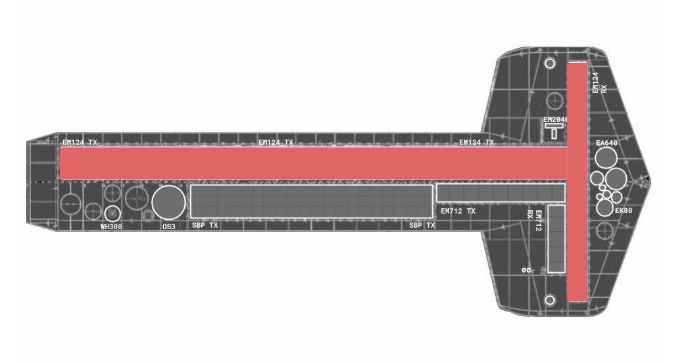
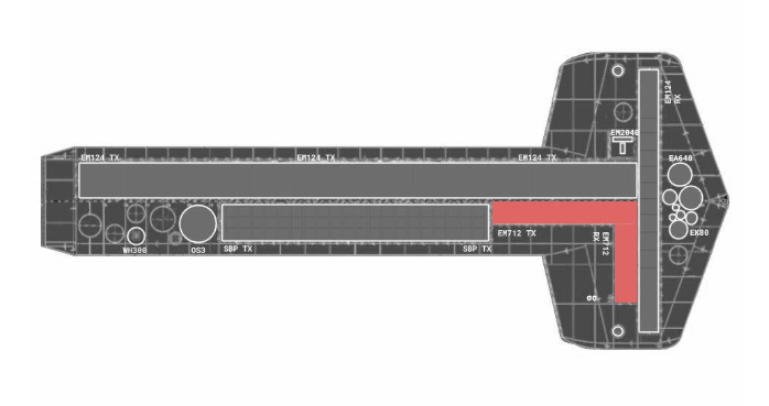
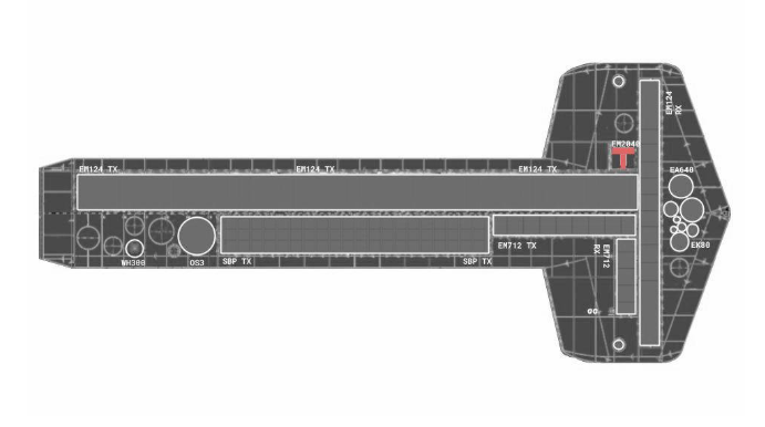
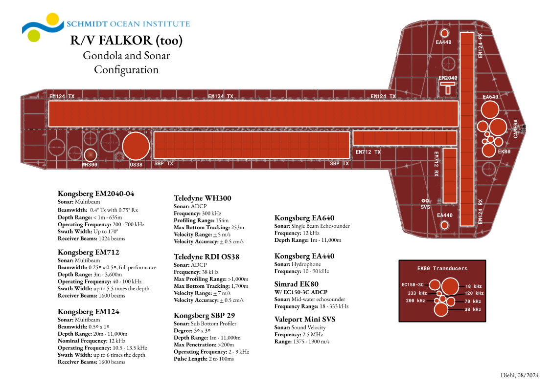
Gondola Technical Drawing
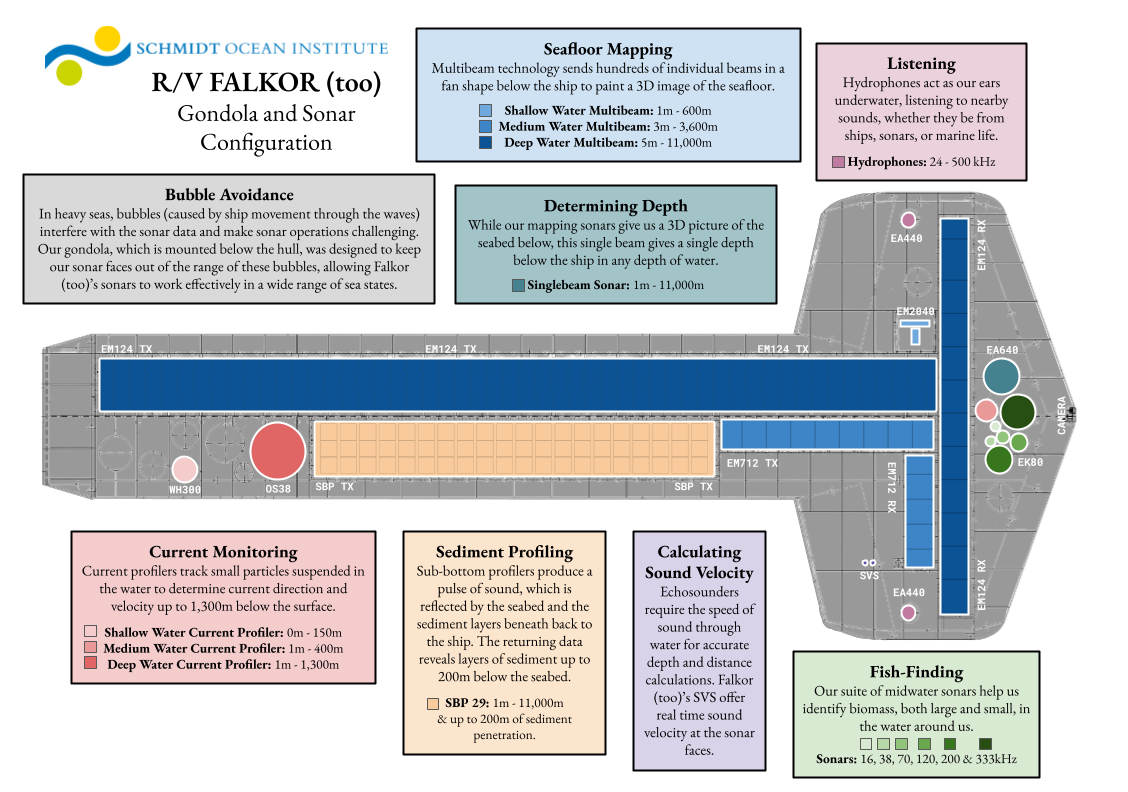
Gondola Outreach Drawing
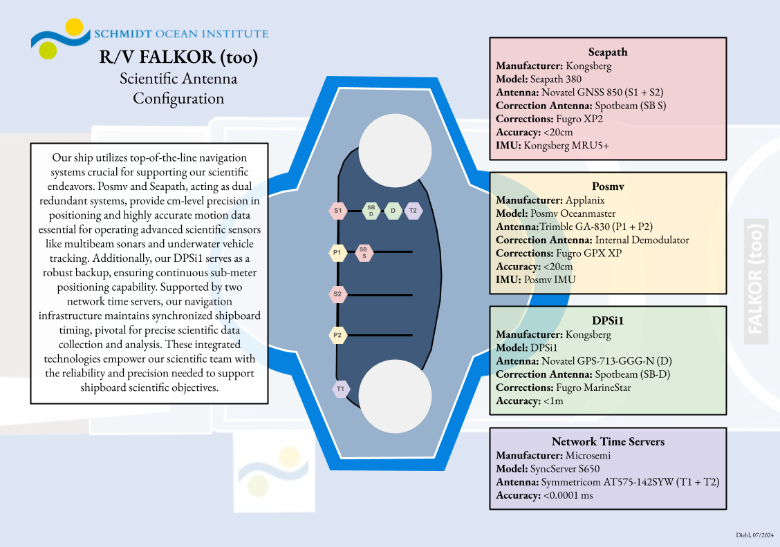
Antenna Plan
Swath Extinction + Tables
Mapping Plan Template Info
R/V Falkor (too) Survey Plan Template Information
Email to mt@falkortoo.org & leadtech@falkortoo.org
The following document is intended to guide science parties into giving key information needed during a multibeam survey so the survey goals can be best met by the ship’s crew. The information below is not required, but is intended to serve as a guide.
Survey Info
Date of Survey:
Estimated Start Time of Survey:
Requested Sonar: See System Descriptions below for specifications.
Requested Survey Speed:
- FKt normal survey speed: 6 knots
- FKt high resolution survey speed: 4 knots
- FKt max distance coverage survey speed: 8 knots
Description of Survey
This is an opportunity to explain the goals and objectives of the survey, which may include/ answer the following prompts:
- Description of the feature/survey area
- Are the goals of the survey to explore an unknown region, to achieve the highest resolution possible, to achieve the highest coverage possible, or a combination?
- Has the survey area been previously surveyed? Is our goal to expand coverage or increase resolution? Mapping sonar/ resolution is helpful if known.
- Depth Ranges of the area if known to aid in choosing the sonar.
- What features, if any, should be prioritized, ex. keeping a ridge line centered.
- Are there any hazards to navigation that would alter how the survey is conducted, for example, rocks, uncharted areas, etc.
Survey Procedures
If you have preferences for how the survey will be carried out, you can explain them here:
What support (if any) will we receive from the science party during the survey?
By default, we log the ‘start/ end of survey’ as well as major settings changes. If you have any specific requirements (ie. line start/stop) please specify.
How would you prefer the ship to handle turns in the survey?
By default, we try to start new lines during turns so the turn data is easier to edit out during post processing, please specify if you want line changes handled a certain way.
If the line coverage is different from planned, for this survey do you want us to ‘edge map’ to eliminate holes or stick to the line plan specified.
If the ETA to the end of the survey is different than planned, would you like the ship to finish the survey or maintain the planned schedule?
- If the survey ended early, should we continue mapping until the scheduled time?
- If the survey won’t be finished by the scheduled time, should we stay longer to finish the survey or break off at the expected time?
Waypoints
Waypoint Number, Latitude, Longitude
- D.DDD is preferred
- If possible, providing the waypoints in a separate txt or csv document will speed up the process of distributing to the bridge/multibeam systems.
An example is below:
Waypoint # Latitude (d.dddd) Longitude (d.dddd) 1 10.1234 -89.9876 2 10.5678 -89.5432 3 10.9012 -89.1098 4 10.3456 -89.7654 5 10.789 -89.7654
Map
If previous multibeam data or satellite data is available a map with our projected survey lines is helpful.
Speed and Distance
1 Kilometer = 0.5939 Nautical Miles
Speed (knots) Time needed for 1 Km 0.5 66 1 33 2 17 3 11 4 8 5 6.5 6 5.5
Additional Tools
System Descriptions
EM2040
- Beam Width: 0.4° Tx with 0.75° Rx
- Depth Range: < 1m - 635m
- Falkor (too) Operating Range: 50m - 200m
- Operating Frequency: 200 - 700 kHz
- Swath Width: Up to 170°
- Receiver Beams: 1024 beams- Our EM2040 is our shallow water multibeam that is generally used in less than 100m of water. For surveys this shallow, we will be syncing the EM2040 with our SU90 (forward facing sonar) with Konsberg’s KSYNC to ensure safe navigation of the vessel.
- For shallow water mapping (less than 100m), we require a line plan that will ensure we stay within the swath of our mapping data and must be organized clearly with the bridge prior to the survey. Near coastal mapping in shallow water must be done during the day and with clearance from the Captain.
EM712
- Beam Width: 0.25० Tx by 0.5० Rx, full performance
- Depth Range: 3m - 3,600m
- Falkor (too) Operating Range: 100m - 1,500m
- Operating Frequency: 40 - 100 kHz
- Swath Width: up to 5.5 times the depth
- Receiver Beams: 1600 beams - Our EM712 is our shallow- mid water multibeam that does best in 100m- 1500m of water.
- The ADCP often causes interference with the EM712, so those should be secured during EM712 surveys.
- The SU90 causes interference with the EM712, so that should be secured during EM712 surveys. In some cases, if the Bridge requires the SU90, we may need to use the EM124 for that survey.
- Performance of the 712 is affected by water depth, vessel noise, sonar cross talk, and sea state. In general, it has to be monitored more closely than our other sonars.
- For features ranging in depth from 300-2000m, we recommend running the EM712 and EM124 synchronized. This also gives the bridge the opportunity to run the SU90 sync’d with EM124.
- For line planning purposes, you can estimate a line spacing of 3x the water depth for the EM712.
EM124
- Beam Width: 0.5० Tx by 1० Rx
- Depth Range: 20m - 11,000m
- Falkor (too) Operating Range: 1,500m - 11,000m
- Nominal Frequency: 12 kHz
- Operating Frequency: 10.5 - 13.5 kHz
- Swath Width: up to 6 times the depth
- Receiver Beams: 1600 beams- Our EM124 is our mid- deep water multibeam that can be synchronized to work with our Sub Bottom Sonar between pings to simultaneously log multibeam and sub bottom data.
- The EM124 does not receive interference from the ADCPs or SU90, which allows those to also be running simultaneously without losing ping density from synchronizing multiple echosounders.
- For line planning purposes, in general you can estimate line spacing of 4x the water depth for the EM124.